The replacement of the UserIO on support arm 3 of the H600 is described
|
|
WARNING! Possible personal injury from untrained operators ⇒ Repairs should only be carried out by individuals with technical and electrical training! |

Benötigtes Werkzeug:
Tools needed:
- 2mm hex key
- 2.5mm hex key
- 10mm Torx bit/key
- 7mm wrench
- Optional: needle-nose pliers
Perform these steps only when the robot is turned off!
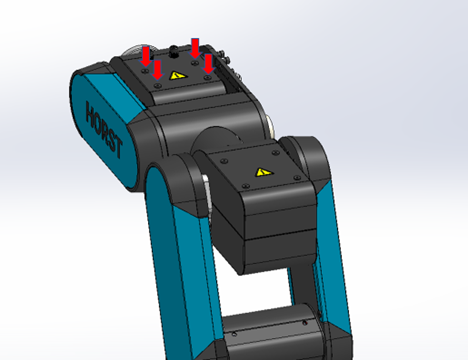
- Start by loosening the four M4 screws that secure the cover on Support Arm 3. These screws are indicated with a red arrow in the image.

- Once the screws are loosened, carefully remove and set aside the cover.
Removing the faulty circuit board:
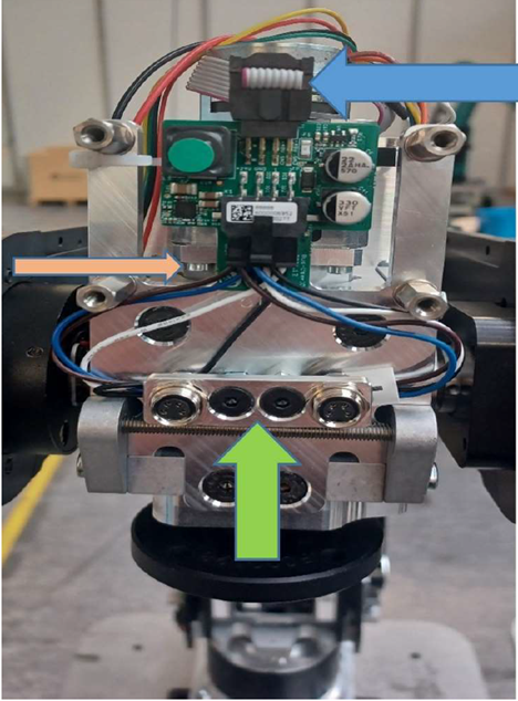
- Disconnect the cable that connects the motor driver to the User IO on the opposite side of the support arm. This cable is indicated by a blue arrow in the image.

-
Disconnect the connectors. Sometimes, the lower spacers may rotate along with them.
If this happens, use a 7mm wrench or needle-nose pliers to counteract it.
The connectors are marked with a green arrow in the image.
- Remove the circuit board from the support arm using a Torx bit. Be careful not to squash or damage the cables with the bit.
-
After loosening all the screws, carefully pull out the circuit board and set it aside.
Make sure to store the board securely to prevent any damage or loss.
Please make sure to proceed with caution during each step to avoid damaging the components. If you are unsure about how to remove the circuit board, it is best to seek help from a professional or contact the manufacturer's customer support for further instructions or assistance.